We were recently called to commission a fully ducted heat recovery ventilation system in a house. The commissioning process was based on CSA-F326, Residential Mechanical Systems to ensure the system didn’t change the pressure in the house and to adjust flows room by room according to the intended mechanical design. In this case the ERV in question was an Enthalpic or Energy Recovery Ventilator (ERV) and what we thought was going to be a straight forward job turned into a multiday, time gobbler that taught us a few lessons.
At risk of stating the obvious, mechanical ventilation systems will either pressurise a home or depressurise it if not commissioned:

The house in the middle is “just right” and had to be commissioned to confirm the ventilation system was “balanced” – that is the pressure inside the house is the same as outside. The house on the left with a “blow only” ventilation system is pressurising the house and possibly driving humidity into the building envelope – which can cause condensation leading to mould, whereas the house on the right with the “suck only” system is pulling in cold dry air from the outside when it’s on.
It should also be noted that NO ONE designs or installs HRV or ERV thinking it might need to be commissioned before occupancy. Typically these units are tucked high into a corner of the basement mechanical room with flex-duct contorted and crammed on all four stations. On flow accuracy, doing a transverse with a Pitot tube comes in 3rd, followed by the more convenient insert type linear type flow measuring station which would come in 2nd place and of course, the best is to install a four quadrant flow measuring station despite the labour involved to re & re.
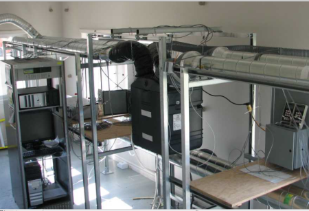
NRCan shows above what the Laboratory set up looks like. Replete with flow straighteners and nice straight lengths of duct before the taps – it won’t look like this in the field.
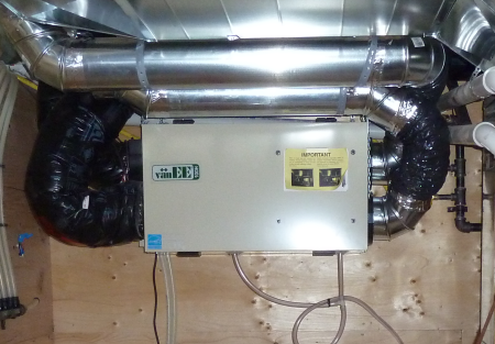
Typical HRV with OK access to ducts.
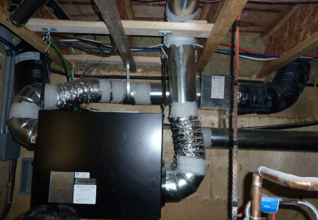
Typical ERV installation with constrained access.

The four quadrants of the ERV for the correct terminology. Thanks AHRI.
So we proposed another method or measuring total air flows. In speaking with the top scientist at ACIN in the Netherlands about our method using the FlowFinder Mk II, it was suggested that the error of the method proposed below could be a bit higher than 3% which given the alternative sounded acceptable and well within CSA-F326 10.2.1′s suggested -+15%!
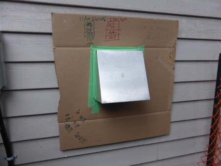
Stations 1 & 4 were the same shape. We taped the cardboard flange to the perimeter of the vent in order to get a reasonably good seal with our balometer. The back-draft dampers were not in the hood, but in the duct. Three sequential measurements were taken to account for potential errors due to wind.
So armed with flow measuring stations, Pitot tubes and our new balometer, we started measuring to find where our TVC might be on the variable speed control board. This would then allow us to adjust flows room by room, except that the flows in and out of the house were off. Way off. They were off at Stations 1 & 4, they were off at Stations 2 & 3.
There were no adjustable dampers for this ERV, so we changed jumpers on the mother board and started undoing duct-work to check that inline back-draft dampers were OK. Still, the flow rates were impossible. We were getting in some cases over a 100cfm more exhaust air (Station 4) than outdoor air (Station 1) and no HRAI ventilation course could have prepared us for what we went through.
In the end, common sense prevailed over a few weeks. Using a Watt meter, we diagnosed something the matter with the control board. The board was replaced and things were better but still not ideal. In the end technical literature suggested that it was common for ERVs with a media wheels to mix in extra ‘purge’ air to combat cross contamination which might explain our difficulties.

Are fan motors blowing air through the media filter or drawing the air through it?
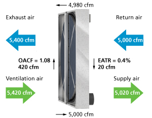
Clearly numbers for a commercial system, but Venmar shows graphically the relationship between air flows.
By design, this meant that flow at station 1 wouldn’t equal flow at station 4. The ratio between those two flows is called the Outdoor Air Correction Factor (OACF) which ideally should stay as close to 1.0 as possible. There’s another cross contamination measurement called the Exhaust Air Transfer Ratio (EATR) - the ratio of the exhaust air transfer to the supply flow rate.
The ERV in question was tested in ‘general’ accordance with CAN/CSA-C439-00, Standard Methods of Test for Rating The Performance of Heat Recovery Ventilators. The OAFC wasn’t available, but the EATR was calculated at 0.09, which according to the manufacturer, translates to about 3% of exhaust air being transferred into the fresh air stream. In other words, if we wanted 100cfm of fresh air delivered, we’d have to bump it up to 103cfm.
This might work in the lab, but not in the field where we were getting differences of 100cfm possibly due to a large OACF, possibly due to the home’s unique, custom duct work and or the added resistance of a pre-heater. Although the ERV in question was tested to CAN/CSA-C439-00, it wasn’t listed as HVI Certified (AHRI if a commercial unit).

In the end, we went with our DG700 and measured the pressure across the building envelope to ensure the system was ‘balanced’ when the ERV was running at TSV. CSA F326 states that flows in and out must be within 10% of each other and typically the flows are measured at stations 2 & 3 if the duct work will allow.
The lessons learned included ensuring the mechanical designer selects an AHRI Certified model and that the heat exchanger core uses a membrane that prevents cross contamination. Measuring flows at stations 4 & 1 or 2 & 3 gave meaningless data because we didn’t know how much of it was due to cross contamination. We were better adjusting flows room by room, then simply ensuring the house pressure was neutral at TVC. Having witnessed the build at the bare duct stage, we knew duct leakage wasn’t an issue, though we could have tested for it. We’re certainly going to ask builders to start supplying a chunk of straight pipe and flow measuring stations at Stations 2 & 3 from now on.
Though it probably applies more to commercial systems, Venmar suggests “If OACF is ignored in the selection process, then the prescribed amount of fresh air will not be supplied to the space and poor indoor air quality may result—in addition to creating numerous potential issues with balancing and commissioning.” and we’d agree on the point about commissioning.
For a through treatment the calculations and explanation of jargon above, AHRI’s How ERVs Work section is brilliant. I’d also recommend downloading and reading NRC’s pdf for insights into the testing process: Evaluation of IAQ Impact of Balanced Residential Ventilation devices that incorporate HRV and ERV.